Wednesday, October 28, 2015

Tunnel Boring Machine (TBM)

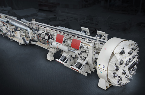
Bored tunneling by using a Tunnel Boring Machine (TBM) is frequently used for excavating long tunnels. Tunneling Boring Machine (TBM) are all the time more used for tunneling with difficult and complex geological environment, including rock and soil mixed and interfaced grounds, bursting rocks, squeezing and swelling grounds, highly rocks fractured , shear and fault zones and grounds under high in situ stress and water pressure.
Tunnel Boring Machine may be suitable for excavating tunnels which contain competent rocks that can provide adequate geological stability for boring a long section tunnel without structural support. However, very hard rock can cause major wear of the TBM rock cutter and may slow down the progress of the tunneling works to the point where TBM becomes useless and uneconomical and may take longer time than the drill and blast tunneling method.


Bored tunneling Benefits
Possible environmental impacts in terms of dust, noise and visual on sensitive receives are much reduced and are restricted to those located near the launching and retrieval shafts
Compared with the cut and cover approach, trouble to local traffic and associated environmental crash would be much reduced

Saturday, October 24, 2015

Road header machine in Construction


A road header machine called a boom type road header. Road headers are advanced, self forced and extremely powerful rock cutting machines are designed to excavate roadways, tunnels and compartments continuously without using volatile. Powered electro hydraulically, they produce no fumes and are used extensively in mineral mining, coal mining and underground construction projects, where their capacity to excavate the desired profile without causing damaging vibrations is highly valued for both safety environmental reasons.
Road header machine

It  is a piece of excavating equipment consisting of a boom mounted cutting head, a loading machine usually involving a conveyor and a crawler travelling track to move the whole machine forward into the rock face. The road header also includes separate part, multi purpose hydraulic cutting heads for increasing on excavators.
The cutting head can be a general purpose rotating drum mounted in line or perpendicular to the boom or can be particular function heads such as jack hammer like spikes, compression fracture micro wheel heads like those on larger tunnel boring machines like a gigantic chain saw for dicing up rock or simple jaw like buckets of traditional excavators.

Construction road headers
Road headers for construction are set with powerful, transverse cutter heads proven to give the best cutting performance in a wide range of rock formations. Subway tunnels, shaft sinking, rehabilitation of existing tunnels, road tunnels and excavation of underground caverns are some examples where these machines have established their great flexibility.


Mining road headers
Road headers for mining are prepared with powerful, transverse cutter heads proven to give an unparalleled cutting performance in a wide range formation of rock. Mounted on an extremely robust hydraulic boom they are reliable, rugged, highly creative result for both development and direct production duties.

Hydraulic cutting heads
Hydraulic cutting heads are designed to be increase on suitable excavators quickly and easily. With transverse cutting structures, tried, geometrically optimized and tested on some of the world’s most rocky mining and tunneling machines, they are well organized, multi use tools for various applications including scaling, production, tunnel treatment, roadway leveling, trenching and demolition.


Sunday, July 12, 2015

Open Channels in Hydralic

There are 2 types of open channels

  1. Man made open channels
  2. Natural open Channels

1. Man Made Open Channels

Man made open channels vary in depth and constant bottom can maintain.
man made open channel

Example of man made open channels

  • Irrigation Channels
  • Navigation Channels
  • Spillways
  • Sewer Pipes
the based field by concrete and surface roughness is well defined.

2. Natural Open Channels

Irregular shapes and bound raises with non Prismatic channels. Surface roughness change place to place and time to time

Example : River

Kind Of Open Channels

  1. Canals
  2. Chutes
  3. Culverts
  4. Tunnels

Saturday, July 4, 2015

Atterberg Limit Test Soil Mechanics

The amount of water in the soil determines the type of soil. There soil can be classified into four states depending on the water content of soil. They are as follows,
  1. Solid
  2. Semi solid
  3. Liquid 
  4. Plastic
Nearly sixty years ago a chemist known as A.Atterberg defined three boundary levels between these four states. They are,
  • Shrinkage limit
  • Liquid limit
  • Plastic limit.
Shrinkage limit is the boundary between solid and semi solid state, liquid limit is the boundary between liquid and plastic state and plastic limit is boundary between plastic and solid state.  The classification of soil is very much important because to determine the engineering properties of soil in Construction technology. In each state the property of soil differs depending on water content. In this situation Atterberg limits helps to identify the state of soil. There are some laboratory tests to find the above mentioned boundary level limits. But in present situation two of the limits are experimented commonly for construction activities. They are plastic limit and liquid limit.
Liquid limit device, Porcelain (evaporating) dish, Flat grooving tool with gage, Eight moisture cans, Balance, Glass plate, Spatula, Wash bottle filled with distilled water, Drying oven set at 105°C.

 Liquid limit test

  • Measure the weight of moisture can and record it.
  • Take an amount of soil in a porcelain dish and add some water in it. Mix them well until get smooth paste. (Soil was passed though a No. 40 sieve and air dried)
  • Level the mixture in the porcelain dish as to get a depth of 1cm.
  • Symmetrically divide the soil sample using the grooving tool.
  • After that, rotate the handle of Liquid limit device so as to get two revolutions per second. 
  • Count the number of blows in which the separated soil sample come into contact to a length of 10mm.
  • Take an amount of soil to moisture can from the above soil sample, where the groove disappeared. 
  • Measure the wet soil sample (+ moisture can) which is taken into moisture can.
  • Keep the soil sample in oven and allow the soil to dry well. 
  • Measure the dry soil sample(+ moisture can) which is dried using oven.
  • Empty the porcelain dish.
  • Repeat the above same procedures to 5 or 6 times by adding water to the same sample.
  • Liquid limit is obtained by plotting graph to number blows (log scale) against moisture content. 

Calculate the moisture content


Picture description of experiment 

Steps A,B

Picture 1 Description of atterberg Test step A,B
Steps C,D


Picture 1 Description of atterberg Test step A,B


Using the points of the graph draw the best straight line through them. Determine the liquid limit by considering the corresponding point on moisture content to the 25 blows.
(Note: According to Casagrande, who developed Atterbergs’ view stated from his experiments that the most exact moisture content is obtained when the number of blows is 25).

Example:


example of Graphs
From the graph, the liquid limit is 28.

Saturday, June 27, 2015

Cost control process

Introduction about cost control

It is very vital to understand the correct meaning of the cost, before moving further about the cost control process. Cost would be based on activities performed in the production or scenarios. (V.Ragasekaran, p.207). This is one of the very useful definitions to analyze in the construction project since it has several activities to be done to get a final product. The basic aim of the cost control is to provide value for money to the respective client not only earning higher profit. It starts with inception stage of the project and continues until agreement of final account. It is very important for construction project because generally all the projects are dealing with huge amount of investment.

Elementary cost control process

According to Nunnally (1998), cost control of a project involves the measuring and collecting the cost record of a project and the work progress. As per the name elementary cost control, it covers analysis of the cost according to the different elements of the building. Generally element of the buildings are sub-structure, super structure, internal finishes, services (mechanical, electrical and plumbing), external finishes, etc.
For the detail explanation the following example is taken. It is stated this example is purely based on the assumption.

Project Name: Sangakara Shopping Mall
Contract Value: LKR 6,000 million (Expected)
Duration: 28 months
Now the elemental cost control process are described in line with the mentioned example.
Cost controlling 

Step one:

This whole process states with anticipated contract sum. In other words it is known as cost limit. In the example it is LKR 6000 Million. Now it is the responsibility of the cost controller to distribute the same as per the elements of the building.


         Element                Cost limit (In LKR million)
Sub-structure                      900
Super-structure                  1600
Internal finishes                 600
Fittings and furniture         950
Services                             1350
External finishes                 700

Step two:

From the above step, it is the time to identify each and every element detail analysis. For example if sub-structure is covering 300,000 m3 of work, cost control team would calculate the cost of the one unit. It is noted in this particular step, specification and drawings should be considered with important.

Step three: 

This step is known as cost monitoring. For an example, as per the step two, cost of the one cubic meter concrete is LKR 20,000.00 It is very vital to check with actual cost. It may be favorable or adverse. If it is adverse, find out the reasons and try to fix the issues. If that also not possible make arrangement to revise the budget. In other way around, if the actual shows as a favorable. It is advised to maintain the same for the whole process.

Step four:

If the whole process will always reviewed and the results shall be communicated to all the project management. Staff for a very effective cost control process.
In conclusion, as per the Austen 1982, the main purpose in cost controlling for a construction project should be active controlling of final costs for owner and not just to record and registering payment. For this achievement, cost reporting is very vital.

Thursday, June 25, 2015

What is FormWork in construction?

Formwork is the mould to shape the concrete structure. Good concrete cannot be made from a poor mould; thus formwork is very important in producing good concrete. Besides that, it has to be designed to take the concrete load and the working load generated from workers and plant.

Column Forwork and support


Timber and plywood were generally used Materials in the site for in-situ concrete work. Columns Beams slabs lift walls and staircases were all constructed using Timber and plywood formwork. Steel casing formwork was used for few structures such as round columns.

The following factors were considered when doing form work;


  •   Correct position
  •   Line and level
  •   Accuracy within permitted tolerances
  •   Shape of members
  •   Verticality (plumb)
  •   Correct angles for batters etc.
  •   Finishing heights (mark off)
  •   Formwork joints flush and tight
  •   No nails protruding into the concrete
  •   Formwork joints sealed as required
  •   Construction joints strutted and supported

All the above formwork was supported with the following false work and other materials   


  • GI pipes, concrete & wire nails
  • Form ties (to tie the separates and GI pipes)
  • Separates (thread bar & P cone)
  • Pipe supports and “T”,”U” jacks
  • adjustable steel props, mould oil (diesel & grease)


Example Form work Cross section of a Column

Example Form work Cross section of a Column

  What are the accessories/tools used in Formwork